
Parallax Scrolling on the Game Boy
This article is a hands-on guide to implementing parallax scrolling on the Game Boy. We'll start by reviewing what parallax scrolling is, and what the challenges are to implement this effect on the Game Boy. Then, we'll go over the implementations of two parallax techniques, the hblank method and the tile method, and explain their respective benefits and drawbacks. By the end of the article, you'll have a strong grasp of what it takes to add parallax scrolling to your Game Boy games.
Preamble
Parallax scrolling is a graphics technique used to create the illusion of depth with 2D graphics.
An example of parallax scrolling is shown in Figure 1.

The main challenge when implementing parallax scrolling on the Game Boy is that the console only features one single layer with scrolling support. In order to implement parallax scrolling, we have to leverage other hardware capabilities and use tricks to mimic the effect of having several scrolling layers.
This article uses code snippets to illustrate the implementation of the two parallax techniques. The full commented source code for the samples is available on GitHub. You will also find prebuilt ROMs there, so that you can run the samples without having to build them first. The ROMs have been tested on both the BGB emulator and real hardware.
The samples are written in assembly for the RGBDS toolchain. You should be familiar with programming the Game Boy in assembly in order to follow along with the code samples. To get a strong introduction to Game Boy programming in assembly, I recommend you to check my book, Game Boy Coding Adventure. It is a complete coverage of all the aspects of programming the Game Boy, using a beginner-friendly approach for those new to assembly.
While the samples are made for the original Game Boy, the techniques they use are relevant to the Game Boy Color too. The concepts introduced in this article should also be suitable to games programmed in C. The techniques presented might even be applicable to other consoles, such as the NES and Master System.
The Hblank Method
The first technique we'll study is the hblank method. Figure 2 is a short video of the hblank sample. It consists of an astronaut walking on an alien planet.
The planets and stars appear to be at a distance, while the rocks appear farther away from us than the ground. To achieve this parallax effect, the idea is to split the screen horizontally into three different layers. The top layer contains the planets and stars. The middle layer contains the rocks. The bottom layer contains the ground on which the astronaut walks. The layers are highlighted with red lines in Figure 3.
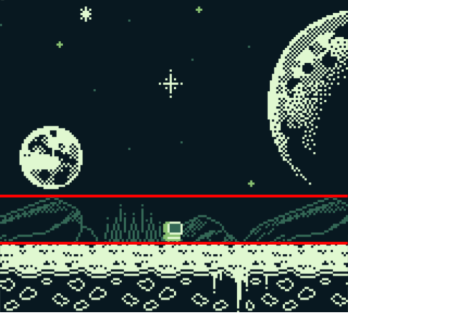
The sky layer extends from lines 0 to 87. The rock spans lines 88 to 111. The ground covers the remaining lines, from 112 to 143. Each layer is scrolled at a different pace when the astronaut walks around in order to create the parallax effect.
For the sample, we use the background graphics shown in Figure 4.

For a basic parallax effect, like the one created by the sample, you can design the background just as you would design a regular background with no parallax. Once you master the basic technique, you can consider designing the three parallax layers separately, based on your game needs. For example, you could have a complex set of ground layers chained together, as the ground will very likely impact the gameplay, while keeping the sky and rocks layers simple, as they will wrap less often due to their lower scrolling speed.
Before we dive into the sample code, let's check the basic algorithm used by the hblank method, and review the hardware features we'll need to implement it.
The algorithm consists of roughly four steps, repeated each frame. First, we'll start by computing the horizontal scrolling values for all three layers based on the movement of the astronaut. Second, during the vblank, we'll set the scrolling value of the background layer to that of the sky, as this is the first layer to be drawn to the LCD. Third, when the LCD refresh reaches the end of line 87, we'll update the scrolling value of the background layer to that of the rocks, as the rocks layer starts on line 88. Finally, when the LCD refresh reaches the end of line 111, we'll update the scrolling value for the ground layer, as that layer starts on line 112. As each layer has its own scrolling value, this algorithm will create a parallax effect.
On the Game Boy, the horizontal scrolling of the background is controlled by the rSCX register.
As mentioned in the algorithm, we'll change the value of that register at very specific times during the frame: the vblank, the end of line 87, and the end of line 111.
We'll use interrupts to properly time the execution of any code modifying the rSCX register.
The Game Boy has five types of interrupts: vblank, LCD, timer, serial, and joypad. For each interrupt, we can provide an associated function that gets called when a particular hardware event occurs. In the sample, we'll leverage the vblank and LCD interrupts, and ignore the other three.
The vblank interrupt triggers when the vertical blanking period (vblank) starts. The vblank is the period of time between the last line of a frame and the first line of the next frame. Nothing is drawn to the LCD during the vblank, which makes it the perfect place to change graphics-related registers that affect the refresh of the LCD.
The LCD interrupt is a kind of umbrella, configurable, interrupt. By umbrella, I mean it is actually linked to more than one hardware event, though all the events it covers are related to the LCD in some way. By configurable, I mean that we can choose which hardware events will trigger the LCD interrupt at any given time. For the hblank sample implementation, we'll use two types of LCD interrupts: the line compare interrupt and the hblank interrupt.
The line compare interrupt triggers at the start of the LCD line we set as target. It does not trigger for lines that are different from the target line. For example, if we set the target line to 100, the LCD interrupt function gets called right before the Game Boy starts drawing that line, and not for any other line. It is an important interrupt for us, as we want to execute code only on specific lines (i.e. 87 and 111).
The hblank interrupt triggers when a horizontal blanking period (hblank) starts. The hblank is a very short period of time at the end of each of the 144 lines of the LCD. During the hblank, nothing is drawn to the screen, and, more importantly, we get full access to the VRAM and graphics-related registers. The hblank is also known as mode 00 and we'll use that term in this article from time to time.
If you've read my book, you might remember that it introduces two versions of the hblank parallax effect:
one naive implementation and one optimized implementation.
The naive implementation uses the hblank interrupt exclusively to set the scrolling value.
The problem with this implementation is that we get interrupts on each line, even though we only need to change the background scrolling on two lines: 87 and 111.
This ends up wasting a lot of cycles that could be better used for actual game logic.
The optimized implementation fixes the performance issue of the naive implementation by using the line compare interrupt.
This implementation reduces the number of interrupts from 144 to 4 during the LCD refresh.
The only issue of the optimized implementation is that it does trigger the rSTAT bug.
The rSTAT bug is a nasty hardware issue that occurs on the original Game Boy.
The bug causes spurious LCD interrupts to trigger when the rSTAT register is written to.
In this article, we'll use a modified version of the optimized implementation, which has the benefit of avoiding the rSTAT bug by writing to the rSTAT register exclusively from inside the interrupt function.
Let's now dive into the sample code. We only review the code relevant to the parallax effect here, but you can always check the full code in GitHub.
The sample declares several constants, as shown in Listing 1.
def LINE_ROCKS                      equ 87
def LINE_GROUND                     equ 111

def SKY_SPEED_X                     equ $0040
def ROCKS_SPEED_X                   equ $0080
def GROUND_SPEED_X                  equ $0100
First, we have two constants, LINE_ROCKS and LINE_GROUND, that define the lines on which we'll change the scrolling values for the rocks and ground respectively.
Then, we define the speeds at which the sky, rocks, and ground moves when the astronaut walks around.
We use 16-bit literals to have a more granular control over the speed of each layer.
Those literals are fixed-point numbers.
The most significant byte of the literal represents the integral part, while the least significant byte represents the fractional part.
Here, GROUND_SPEED_X represents the number 1.0, ROCKS_SPEED_X represents 0.5, and SKY_SPEED represents 0.25.
The sample uses several variables to store the layers' scrolling values.
In the sample, all the variables are stored in WRAM, but you could also put them in HRAM and benefit from the ldh instruction.
The variables are shown in Listing 2.
rsset _RAM
    ...

    def WRAM_SKY_POSITION_X             rb 2
    def WRAM_ROCKS_POSITION_X           rb 2
    def WRAM_GROUND_POSITION_X          rb 2

    def WRAM_ROCKS_SCROLLING_X          rb 1
    def WRAM_GROUND_SCROLLING_X         rb 1
First, we have the three fixed-point numbers to hold the positions of each layer.
We'll see how these get updated soon.
Then, we have two buffer variables.
These hold the values meant to be copied to the rSCX register during the hblank interrupts.
Their value is basically equal to the high bytes of the corresponding positions.
For example, WRAM_ROCKS_SCROLLING_X holds the high byte of WRAM_ROCKS_POSITION_X.
The reason we don't use the positions' high byte directly in the interrupts is that we need to keep the scrolling values stable during the LCD refresh, at least until line 112.
Because the positions might get computed in the sample's main loop before the interrupts get triggered, we need to copy their value to those buffer variables that are guaranteed to be stable through the LCD refresh.
Note that we don't need a buffer variable for the sky, because the scrolling for the sky is set before the LCD refresh even starts (i.e. during vblank).
At initialization time, all the WRAM variables are cleared to zero. The sample also sets the interrupts as shown in Listing 3.
ld a, LINE_ROCKS
ldh [rLYC], a

ld a, STATF_LYC
ldh [rSTAT], a

ld a, IEF_VBLANK | IEF_LCDC
ld [rIE], a
ei
First, we set the target line (rLYC register) for the line compare interrupt to the value of the rocks line (LINE_ROCKS).
The target line changes through the frame, but at the start of every frame, it is always set back to LINE_ROCKS, because that's the first line on which we need to change the value of the rSCX register to produce the parallax effect.
Then, we raise the flag for the line compare interrupt in the rSTAT register.
This is an essential step to enable the line compare interrupt, which is one type of LCD interrupt.
Note that the hblank flag isn't raised yet in the rSTAT register.
We don't want hblank interrupts to trigger on each line as it would waste cycles.
We'll raise the hblank flag during the LCD refresh, only when necessary.
Finally, we enable both the vblank and LCD interrupts.
The vblank interrupt is essential for frame pacing, and we also use it each frame to prepare for the next line compare and hblank interrupts.
In the sample's main loop, we compute the positions of all the layers for the next frame, as shown in Listing 4.
.astronaut_move
    ld a, [ASTRONAUT_MOVE_DIRECTION]
    cp a, DIRECTION_LEFT
    jr nz, .direction_left
        u16_sub WRAM_SKY_POSITION_X, SKY_SPEED_X
        u16_sub WRAM_ROCKS_POSITION_X, ROCKS_SPEED_X
        u16_sub WRAM_GROUND_POSITION_X, GROUND_SPEED_X
        jr .astronaut_move_done
    .direction_left
    cp a, DIRECTION_RIGHT
    jr nz, .direction_right
        u16_add WRAM_SKY_POSITION_X, SKY_SPEED_X
        u16_add WRAM_ROCKS_POSITION_X, ROCKS_SPEED_X
        u16_add WRAM_GROUND_POSITION_X, GROUND_SPEED_X
    .direction_right
.astronaut_move_done
We add or subtract the speeds to the layer positions based on the direction the astronaut is walking to.
The u16_add and u16_sub macros handle the fixed-point arithmetic.
You can check their code in the GitHub repository.
The updated positions are used during the vblank to prepare for the interrupts. The relevant vblank code is shown in Listing 5.
ld a, [WRAM_SKY_POSITION_X + 1]
ld [rSCX], a

ld a, [WRAM_ROCKS_POSITION_X + 1]
ld [WRAM_ROCKS_SCROLLING_X], a
ld a, [WRAM_GROUND_POSITION_X + 1]
ld [WRAM_GROUND_SCROLLING_X], a
First, we update the rSCX register so that it has the sky scrolling value when the LCD refresh starts.
Then, as mentioned earlier, we use buffer variables, WRAM_ROCKS_SCROLLING_X and WRAM_GROUND_SCROLLING_X, to keep the scrolling values for the rocks and ground layers stable during the whole LCD refresh, and in particular, for the corresponding hblank interrupts.
The final piece of the algorithm is the LCD interrupt function, which handles both the line compare interrupts and the hblank interrupts. The complete function is shown in Listing 6.
LcdInterrupt:
    ldh a, [rSTAT]
    bit STATB_MODE00, a

    ld a, STATF_MODE00
    ldh [rSTAT], a

    ret z

    ld a, [rLY]
    cp a, LINE_ROCKS
    jr nz, .middle_section
        ld a, [WRAM_ROCKS_SCROLLING_X]
        ldh [rSCX], a

        ld a, LINE_GROUND
        ldh [rLYC], a

        ld a, STATF_LYC
        ldh [rSTAT], a

        ret
    .middle_section

    ld a, [WRAM_GROUND_SCROLLING_X]
    ldh [rSCX], a

    ld a, LINE_ROCKS
    ldh [rLYC], a

    ld a, STATF_LYC
    ldh [rSTAT], a

    ret
This interrupt function is called four times per LCD refresh. It is easier to understand the code by going through each interrupt that occurs during the LCD refresh in order.
The first interrupt to occur during the LCD refresh is the line compare interrupt on line 87, which we set up at initialization time.
The role of the line compare interrupt on line 87 is only to enable the hblank interrupt for that same line, because we cannot safely update the rSCX register during a line compare interrupt.
The reason is that the value of the rSCX register is read in a peculiar way by the hardware.
The lower three bits of the register are read at the start of the line, while the remaining five bits of the register are read several times over the drawing of the line.
As a consequence, the only place where it is safe and correct to change the value of the rSCX register is the hblank of line 87.
The line compare interrupt on line 87 is handled by the first five instructions in the interrupt function, shown in Listing 7.
ldh a, [rSTAT]
bit STATB_MODE00, a

ld a, STATF_MODE00
ldh [rSTAT], a

ret z
These instructions have two purposes: they enable the hblank interrupt and they return early if we are not in the hblank yet.
The first two instructions check if the hblank flag, also known as mode 00 flag, is set in the rSTAT register.
If the hblank flag is clear, then the CPU zero flag gets raised.
Otherwise, the CPU zero flag gets cleared.
In the case of the line compare interrupt on line 87, the flag gets cleared, because we are not in the hblank yet.
The next two instructions enable the hblank interrupt, so that a hblank interrupt triggers at the end of the line.
The last instruction returns early, because we are not yet in a hblank interrupt, which means the zero flag has been raised by the bit instruction.
The next interrupt to trigger is the hblank interrupt on line 87.
As we've just seen, this interrupt was enabled by the line compare interrupt at the start of line 87.
The execution goes through the same exact first five instructions, but the function does not return early this time, because the hblank flag is up in the rSTAT register.
The CPU additionally executes the instructions in Listing 8.
ld a, [rLY]
cp a, LINE_ROCKS
jr nz, .middle_section
    ld a, [WRAM_ROCKS_SCROLLING_X]
    ldh [rSCX], a

    ld a, LINE_GROUND
    ldh [rLYC], a

    ld a, STATF_LYC
    ldh [rSTAT], a

    ret
.middle_section
The code first checks whether the interrupt occurred on line 87 (LINE_ROCKS).
As this is the case in the hblank of line 87, the six instructions right after the jr instruction get executed.
First, the rSCX register is updated with the scrolling value for the rocks.
Then, the target line for the line compare interrupt is set to 111 (LINE_GROUND) and the line compare interrupt is re-enabled, so that we get a line compare interrupt on line 111.
Note that the hblank interrupt is disabled here (the flag is not raised in rSTAT).
This is important, because we don't want to trigger hblank interrupts on lines 88 to 110 for performance reasons.
Finally, the function returns, as there is nothing else to do to handle the rocks layer.
The next interrupt occurs on line 111. This is the line compare interrupt that has been set up in Listing 8. That new line compare interrupt is handled by the code in Listing 7, just like the line compare interrupt on line 87. The interrupt function basically enables the hblank interrupt and returns early.
The last interrupt of the frame is the hblank interrupt on line 111. This time the function does not return early, and goes through the instructions shown in Listing 9.
ld a, [rLY]
cp a, LINE_ROCKS
jr nz, .middle_section
  ...
.middle_section

ld a, [WRAM_GROUND_SCROLLING_X]
ldh [rSCX], a

ld a, LINE_ROCKS
ldh [rLYC], a

ld a, STATF_LYC
ldh [rSTAT], a

ret
Because we are now on line 111, the jr nz, .middle_section does jump to the .middle_section label.
The instructions at the end of the function then get executed.
These instructions are very similar to those in Listing 8, with only two differences.
The first difference is that the rSCX register gets updated with the scrolling value for the ground.
The second difference is that the target line for the line compare interrupt is brought back to 87 (LINE_GROUND), to prepare for the next frame.
And that's it for the hblank method.
All subsequent frames will go through the same series of updates and interrupts.
The hblank method relies on the proper usage of the line compare and hblank interrupts to update the rSCX register at key times during the frame to create the parallax effect.
The advantage of this method is that it is well supported by the hardware.
The LCD interrupts make the code efficient, and we only need a handful of instructions and variables to implement the parallax.
You could easily add more layers, but remember that each additional layer will consume some cycles for the variable updates and additional interrupts, so there will be less cycles left for the game logic.
The main drawback of the hblank method is that layers cannot overlap.
To get overlapping elements, you'd have to use sprites, with all the limitations that apply to them.
The Tile Method
The second parallax technique we'll study in this article is the tile method. It is a completely different approach to parallax scrolling than the hblank method. It comes with its own benefits and drawbacks, but it does not fail to create an impressive parallax effect.
Figure 5 is a short video of the tile sample. The astronaut is back, but this time, he walks in a warehouse.
The floor and boxes are in the foreground and move quickly as the astronaut walks around. The wall in the background moves at a slower pace, which creates the parallax effect. We have two layers of parallax, and the nice aspect of the tile method is that those layers can overlap.
To implement the tile method, we don't need to use any LCD interrupt, and we don't even need to change the value of the rSCX register during the LCD refresh.
The method entirely relies on designing tiles that can fake parallax and on transferring the right tiles every frame to VRAM.
During development, we design a pattern of tiles that we want to scroll in the background. Then, we create all the combinations of tiles we need to cover the scrolling of the background. At runtime, we compute the combination of tiles we need to display during the next frame. Then, during the vblank, we copy over that combination of tiles to VRAM.
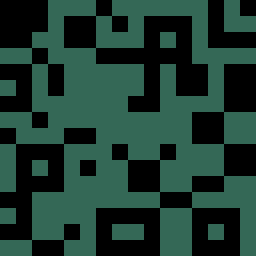
Before we jump into the sample's code, let's check how to author the tile pattern for the background. For the sample, we use the 16x16 repeating pattern shown in Figure 6.
For the tile sample, we need all the horizontal combinations of this pattern. As we use a 16-wide pattern, there are 16 such combinations. Each combination is built upon the previous one, starting with the combination in Figure 6. The rightmost column of pixels is copied to the leftmost position. The other pixel columns are, in effect, all shifted one pixel to the right. The process to generate the second tile pattern is illustrated in Figure 7.
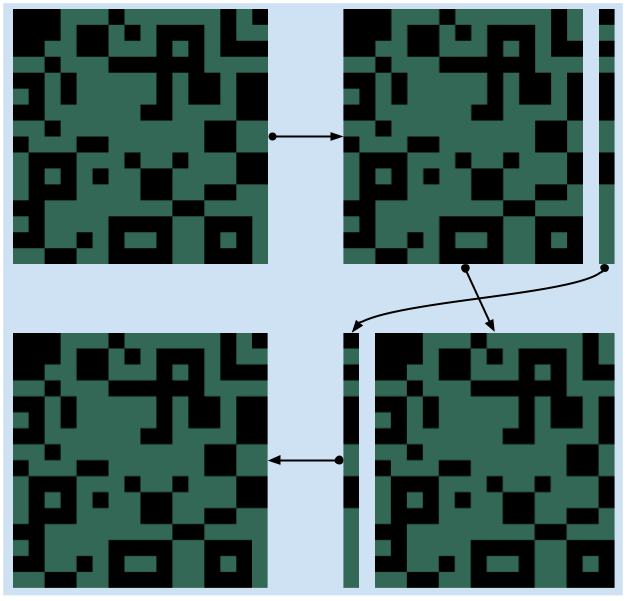
Following the arrows, the second pattern is built from the original pattern that we want to scroll. We first knock out the rightmost column of pixels from the original pattern. Then, we bring that column to the front of the other fifteen columns, which we move one pixel to the right, to form a new pattern. The second pattern is then used to create the third pattern, using the exact same steps, and so on, until we have 16 patterns. Figure 8 shows all the 16 patterns used in the sample.

In the sample, these patterns are included in the ROM in order. The four tiles of a pattern are ordered as well. The top left tile comes first, then the top right one, followed by the bottom left one, and finally, the bottom right one.
Let's dive into the code of the sample and see what it takes to implement a parallax effect using the tile method. The sample uses a few constants, shown in Listing 10.
def BYTES_PER_TILE                  equ 16
def WALL_TILE_COUNT                 equ 4

def FOREGROUND_SPEED_X              equ $0100
def BACKGROUND_COUNTER_SPEED_X      equ $0080
The number of bytes per tile, BYTES_PER_TILE is not specific to this algorithm, but it is not declared anywhere else, and we need it for formulas we'll see later.
The WALL_TILE_COUNT constant corresponds to the number of tiles in the pattern from Figure 6.
The two remaining constants are the speed of the parallax layers.
The FOREGROUND_SPEED_X variable applies to the foreground, which consists of the floor and the boxes.
The BACKGROUND_COUNTER_SPEED_X variable is for the background, which corresponds to the wall covered by the tile pattern.
It is named counter speed because it represents the speed of the background relative to the foreground.
When it is equal to $0000, the background would move in unison with the foreground.
That is, there would be no parallax effect.
With a counter speed equal to the foreground speed ($0100 here), the background would be fixed to the LCD, not moving at all.
In the sample, the counter speed is set to half the speed of the foreground, which creates a smooth parallax effect.
Feel free to try different values to see how it works.
It is even possible to make the background move faster than the foreground by setting a counter speed higher than $0100.
Next, the sample declares a few variables in WRAM, as shown in Listing 11.
rsset _RAM
    ...

    def WRAM_FOREGROUND_POSITION_X      rb 2
    def WRAM_BACKGROUND_POSITION_X      rb 2

    def WRAM_WALL_STARTING_TILE_ADDRESS rb 2
The first two variables are 16-bit numbers used to track the positions of both layers.
Like in the hblank parallax sample, these are fixed-point numbers with their high byte dedicated to the integral part of the number.
The WRAM_WALL_STARTING_TILE_ADDRESS variable holds the starting ROM address of the tiles we need to transfer to VRAM to create the parallax effect of the background.
Let's see how all these variables are computed next, starting with the layer positions in Listing 12.
.astronaut_move
    ld a, [ASTRONAUT_MOVE_DIRECTION]
    cp a, DIRECTION_LEFT
    jr nz, .direction_left
        u16_sub WRAM_FOREGROUND_POSITION_X, FOREGROUND_SPEED_X
        u16_sub WRAM_BACKGROUND_POSITION_X, BACKGROUND_COUNTER_SPEED_X
        jr .astronaut_move_done
    .direction_left
    cp a, DIRECTION_RIGHT
    jr nz, .direction_right
        u16_add WRAM_FOREGROUND_POSITION_X, FOREGROUND_SPEED_X
        u16_add WRAM_BACKGROUND_POSITION_X, BACKGROUND_COUNTER_SPEED_X
    .direction_right
.astronaut_move_done
This code is very similar to the code in the hblank sample.
We add or subtract the speeds to the layer positions based on the direction of the astronaut.
Again, you can check the code for the u16_add and u16_sub macros in the GitHub repository.
The computation of the WRAM_WALL_STARTING_TILE_ADDRESS variable is shown in Listing 13.
.compute_wall_tile_address
    ld a, [WRAM_BACKGROUND_POSITION_X + 1]
    and a, $0F

    swap a
    ld h, 0
    ld l, a
    add hl, hl
    add hl, hl

    ld de, ship_parallax_chr
    add hl, de

    ld a, l
    ld [WRAM_WALL_STARTING_TILE_ADDRESS + 0], a
    ld a, h
    ld [WRAM_WALL_STARTING_TILE_ADDRESS + 1], a
.compute_wall_tile_address_done
The first two instructions compute the index of the tile combination we need for the next frame from the position of the background layer. They are equivalent to a modulo 16 of the position, because we only have 16 tile combinations.
The next set of five instructions computes the offset of the tile combination in memory from the tile combination index.
All these instructions are basically a multiplication by 64, because we have 16 bytes per tile and 4 tiles per tile combination.
The swap a instruction is an efficient way to multiply by 16.
The multiplied number must be below 15, which is guaranteed to be the case here, because of the modulo 16 applied above.
The number is then put in the hl register and added to itself twice, which is equivalent to multiplying it by 4.
At the end of those instructions, we do have the desired offset in the hl register.
Once we have the offset, we add it to the base address of the tiles in the ROM, ship_parallax_chr, to get the actual address of the tile combination we need to copy over to VRAM.
However, we can't copy the data to VRAM just yet.
We need to perform the copy during the vblank, when we have write access to VRAM.
The last four instructions save the starting address we computed to WRAM, so that we can use it during the next vblank.
The last piece of the tile parallax method is the vblank, shown in Listing 14.
ld a, [WRAM_FOREGROUND_POSITION_X + 1]
ld [rSCX], a

ld a, [WRAM_WALL_STARTING_TILE_ADDRESS + 0]
ld l, a
ld a, [WRAM_WALL_STARTING_TILE_ADDRESS + 1]
ld h, a
ld de, _VRAM8800
ld c, BYTES_PER_TILE * WALL_TILE_COUNT
.copy_wall_tiles
    ld a, [hli]
    ld [de], a
    inc de
    dec c
    jr nz, .copy_wall_tiles
During the vblank, the rSCX register is updated to reflect the movement of the foreground.
The parallax tiles are also copied over to VRAM.
The source address computed earlier is first unpacked in the hl register.
Then, 4 tiles, or 64 bytes (BYTES_PER_TILE * WALL_TILE_COUNT) of data, are copied to VRAM.
The destination address in VRAM is $8800, because that's where the background pattern tiles are located in the sample.
You can verify the location of the pattern tiles with BGB's VRAM viewer, as shown in Figure 9.

The four pattern tiles are highlighted in red. Every frame, we update those four tiles with the tile combination that matches the desired scrolling of the background layer. This tile update creates the parallax effect.
That's it for the tile method. At its core, it is all about copying the right tiles from ROM to VRAM each frame. It creates a very convincing parallax effect by just swapping the tile graphics used for the background. The benefit of the technique is that layers can overlap. Another benefit is that the technique also allows for vertical parallax, such as those used in vertical shmups. It is even possible to design parallax effects in both directions. The main drawback is the amount of ROM space you need to dedicate to the tile combinations. The ROM space budget can quickly balloon out of proportion as the tile pattern grows in size, or is allowed to scroll in both directions. It is possible to update the tile indices in the tilemap (in addition to the tile graphics) to mitigate the ROM space consumption, but that requires more complex code. Another drawback is that the technique adds a lot of workload in the vblank, leaving less cycles for any other work, such as sprites or tile animation. On the Game Boy Color, it is possible to use DMA to make those transfers way faster.
Conclusion
In this article, we covered two techniques to create parallax effects on the Game Boy. You should now have a good grasp of how to implement both techniques. You should also understand their benefits and drawbacks, and be able to choose the right technique for your games. It is possible to mix both techniques together too, and several commercial games did so.
This article introduced the basis of both techniques, but it is always possible to tailor and improve upon these techniques to match your specific needs and create more impressive effects.
One thing to keep in mind is to not make any layer scroll too quickly. The Game Boy LCD suffers from heavy ghosting, and the blurring of your art would waste the parallax effect.
If the content of this article feels overwhelming, you might want to check my book. It is a smooth introduction to basically everything there is to say about Game Boy programming.
Art Attribution
The backgrounds used in the samples are from Rumblecade. The astronaut character is from Dizabanik Games. The art has been slightly modified to meet the limitations of the Game Boy hardware.